Writing an OS: Baby Steps

(Taken from the excellent movie, What About Bob?)
This tutorial is intended to walk you through writing your own very simple operating system in assembly. I originally found the basis of this tutorial on the OSDev wiki, but it didn’t have any explanation to what was going on or why, so I decided to make this tutorial. We’ll go over the basics of the booting process and what tools you’ll need to operate.
Most popular operating systems like OSX, Linux, or Windows contain drivers and provide interfaces to the hardware, ensure a certain level of safety and security, keep the processes from fighting each other, and provide essential libraries for programs to use the computer. However, ours won’t be nearly as complicated. :) By the end of this tutorial, you should have an operating system that prints a message to the screen!
I attempted to explain everything as simple as possible, but if I made any errors or you’d like to suggest changes to my article, feel free to make an issue on Github or email me.
The source code is also available in this Github repository.
Table of Contents
- Table of Contents
- Requirements
- The Booting Process
- Finally, Some Code
- Shortening the Build Process
- Printing to the Screen
- What is a segment?
- Back to Our Code
- Exercises
- Further Reading
Requirements
This tutorial assumes that you already have a Debian-based Linux installation. However, the main part that shouldn’t change much between other Linux distributions except for the method of installing. If you don’t you can still follow along by installing Ubuntu in a virtual machine or by using Michali Sarris’s comment to use Docker Toolbox.
You’ll need nasm, build-essential, and qemu.
$ sudo apt-get install nasm build-essential qemunasmis an assembler, which translates assembly code into binary code that the computer can directly executebuild-essentialinstalls many programs and compilers required for building other programs. We will usemakemostly to automate building the operating system and running itqemuis an easy to use virtual machine that emulates a computer, so that we don’t have to accidentally screw up our computer or reboot constantly to develop our operating system. We can test the code out directly on the virtual machine that the qemu software provides
The Booting Process
When a computer is first powered on, it starts up in a processor mode called Real Mode. This mode is a legacy left over from when we used 16-bit computers and forces the processor to use 16-bits while it’s in that mode. A byte is 8 bits, which are numbers that can be either 1 or 0 and are encoded as binary numbers. For example: 10010101 is a byte. Computers use bits and bytes to deal with instructions and data because that format is analogous to off and on. A computer is basically an incredibly dense electronics circuit, so using binary to program it works out well to map most directly to the hardware. This mode can’t access much RAM memory because the smaller amount of bits means a smaller amount of available numbers for addresses to use when accessing the ram. Most computers today which are 32-bit or 64-bit can access at least 4GB of RAM memory, while most 16-bit computers accessed 1MB worth of RAM. For our purposes, Real Mode is fine because it’s the only mode which allows us to use BIOS functions and we’re going to use relatively simple code.
After the computer powers on, it loads the BIOS (Basic Input Output System) from a special permanent flash memory chip on the motherboard in Real Mode. the BIOS functions as a rudimentary library that can access and modify hardware on the computer. The BIOS also performs a POST (Power On Self Test) check to make sure that all systems are running fine. It then locates the MBR (Master Boot Record, also known as boot sector) which is 512 bytes long and always found at the very start of the bootable media like a hard drive, floppy, dvd, or usb drive. After finding it, the BIOS executes the code in the MBR in Real Mode.
The MBR has many functions located inside it. It can hold the locations and information of different partitions for the hard drive and it also holds the code that the computer executes. Because the MBR is only 512 bytes and most operating systems don’t fit into that size (Linux and Windows contain millions of lines of code), many operating systems use a bootloader that can load the operating system kernal code from different filesystems and execute it, while finishing the set up of the computer.
Our little operating system kernel, however, will fit inside the 512 bytes, so it doesn’t need a bootloader to load more code from the disk.
What I’ll do is show you some code and we’ll deconstruct it bit by bit. Don’t worry if you don’t understand everything; this is meant to just give you some knowledge about how computers work. I’ll also provide the commands and information so that you can follow along on your own computer.
Finally, Some Code
Type this snippet into your favorite text editor as boot.asm:
 1 ; boot.asm
 2 hang:
 3     jmp hang
 4
 5     times 510-($-$$) db 0
 6
 7 	; This is a comment
 8
 9     db 0x55
10 db 0xAAhang:is just a named marker in the codejmp hangmeans jump to the hang marker- This makes an infinte loop
times 510-($-$$) db 0is NASM syntax for fill the rest of the remaining bytes up with zeroes$means start of the current line$$references the start of the file/section($-$$)means subtract the current location from the beginning of the file- We don’t use
512to fill up the rest of the MBR’s 512 bytes because the twodbcommands afterward store two bytes at the end
- Anything that follows a
;is a comment and is disregarded by the assembler when assembling the source code file 0x55and0xAAare ‘magic bytes’ that tell the BIOS, “Yes, this is a executable MBR”
As you can see, the assembly code is generally executed sequentially except for parts where instructions jump to other pieces of code.
Enter this into the command line to assemble the file into a binary file that the computer can actually execute:
$ nasm -f bin boot.asm -o boot.bin-f binensures that nasm assembles it into the binary format instead of something like elf which is used for general purpose programs in Linuxboot.asmis the source code assembly file that nasm is trying to assembleboot.binis the output file name
Then we start qemu with this file:
$ qemu-system-x86_64 boot.binqemu-system-x86_64is used because we want to use the version of qemu that provides a 64-bit computerboot.bintells qemu to use boot.bin as bootable media
You should see this screen when qemu starts up, if your program was successful.
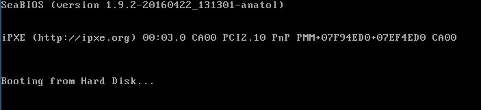
So, what this program does is make the computer go into an infinite loop and hang. Not too bad, right?
Shortening the Build Process
That was a lot of commands you typed in the command line earlier just to get your operating system to run. Let’s make it shorter.
We’ll do this with make, a program that is for setting up build toolchains for almost anytype of compilation.
First, let’s make a file named Makefile and put this into it:
1 boot.bin: boot.asm
2 	nasm -f bin boot.asm -o boot.bin
3
4 qemu: boot.bin
5 	qemu-system-x86_64 boot.bin
6
7 clean:
8 	rm *.bin
The values before the colons are names for the list of commands that come afterwards. This way you can type make clean and make will execute rm *.bin for you, which removes all of the assembled files.
The values that come after the colon are dependencies. So when you type make qemu, make will execute boot.bin’s commands (nasm -f bin boot.asm -o boot.bin) before it executes qemu-system-x86_64 boot.bin.
Printing to the Screen
Change your boot.asm assembly file, so that it looks like this:
 1 ; boot.asm
 2 mov ax, 0x07c0
 3 mov ds, ax
 4
 5 mov ah, 0x0
 6 mov al, 0x3
 7 int 0x10
 8
 9 mov si, msg
10 mov ah, 0x0E
11
12 print_character_loop:
13     lodsb
14
15     or al, al
16     jz hang
17
18     int 0x10
19
20     jmp print_character_loop
21
22 msg:
23     db 'Hello, World!', 13, 10, 0
24
25 hang:
26     jmp hang
27
28     times 510-($-$$) db 0
29
30     db 0x55
31     db 0xAA
Now use make clean and make qemu to clean, assemble, and run your operating
system.
I know this looks daunting! We’ll go through it line by line though.
I’ve separated the code by chunks that correspond with the surrounding instructions. We’ll go over each chunk and the instructions used, so that we can figure out how the operating system goes about printing to the screen.
If you look at some of these instructions, they have certain pieces information behind them. These are called operands. In NASM syntax, the right operand is the source operand and the left one is the destination operand. The letter operands refer to registers in the CPU, which are special places that hold bits of information the computer can operate on.
mov is an instruction that moves data around. It can move bytes from
register to register and from locations in the code to registers.
Let’s use this knowledge to figure out our first chunk:
1 mov ax, 0x07c0
2 mov ds, ax
In the first line, we move the value 0x07c0 into the register ax. 0x07c0 is
a hex value, which is a different number format and more convenient for assembly programmers to use than
raw binary numbers of 1s and 0s.
Then we copy the value from register ax to register ds. You might ask,
“Nick, why don’t you just copy 0x07c0 directly into register ds?” Well,
ds is a very special register. It stands for data segment, and for some
reason known only to Intel developers, it can only have values transfered to it
from other general purpose registers.
What is a segment?
Segmentation is a special feature of Real Mode, which Intel made to keep their 16-bit processor, and allow users to be able to access more memory. Traditionally when a computer is 16-bit, only 16-bits are used in the addressing lines, which call data storage devices with an addresses (in binary) to get certain values stored at the address in the storage device. Because computers use binary, a 16-bit addressing scheme would mean that there are only 2^16 available slots in which to store a byte. This equates to 64KB of RAM memory. Those crafty Intel developers implemented segementation to allow the computer to access 20 bits worth of addressing space which is 2^20 addresses or 1MB worth of memory.
However, this comes at a cost of using the segmentation
feature. To keep 16-bit compatibility, the processor has to use two registers to
store the segment and the offset. The register that holds the segment is
multiplied by 0x10 (16 in the decimal format, which is what we use to count), to add another zero to the end of the hex number. Multiplying by 0x10 translates to adding four zeros to the end of the number in binary. This means that the 16 bit number is now 20 bits!
The offset is then added to the segment address to get the actual location.
So, when the offset is added to the segment, the address can change those four zero bits at the end to any number to access all the addresses in a 20-bit address space.
A helpful way to visualize this by dividing 1MB or 1024KB by 16. This gives us 64KB and shows us that with segements, we can set the segement to any address in the processor to access the RAM in 64KB blocks with the offset being able to access any address inside those blocks of 64KB.
A segmented address is generally referred to in this format
segment:offset.
Back to Our Code
1 mov ax, 0x07c0
2 mov ds, ax
Now you should see that this chunk of code loads 0x07c0 into register
ds, or data segment, for segment addressing. But, why would we need this?
Some BIOS functions require the location of the code stored into the ds register to access it later. The code is located at 0x07c0:0x0000 always because that’s where the BIOS loads the MBR every time.
Here’s another chunk:
1 mov ah, 0x0
2 mov al, 0x3
3 int 0x10
Here we encounter int, another new instruction. It stands for interrupt
and it interrupts the CPU and calls a certain piece of
code referred to as an interrupt handler. Usually that interrupt handler uses pieces of code in registers to do
operations like taking the character in a register and printing it to the screen. In our case, the interrupts are already mapped to functions that the BIOS
has setup for us earlier.
int instructions only take one operand and that refers to the interrupt
number. 0x10 is the BIOS interrupt that manages video services like writing
characters to the screen, clearing it, setting the video mode and size, among
other functions depending on the value stored in ah. The numbers that affect
operation of the BIOS functions are usually
just chosen without rhyme or reason, so don’t be afraid to look up information
about the BIOS interrupt you’re using online.
0x0in registerahrefers to setting the video mode and size.0x3in registeraltellsint 0x10that the video size should be 80 characters by 25 characters.
These lines get us set up for the character printing loop:
1 mov si, msg
2 mov ah, 0x0E
In the first line, we move the pointer to the address of our message we want to print into the
si register. We use si because the lodsb instruction uses the
segemented address ds:si to load a byte from that location.
mov ah, 0x0E uses the ah register again. 0x0E in the register ah lets us
use the 0x10 interrupt for printing characters to the screen.
This is referred to as teletype output because it emulates the
functionality of a teletypewriter, which is similar to how a typewriter
operates, but able to send the text to a computer or printer.
Finally, we’re at the part where we actually print characters to the screen:
1 print_character_loop:
2     lodsb
3
4     or al, al
5     jz hang
6
7     int 0x10
8
9     jmp print_character_loop
The lodsb instruction loads a byte into register al from the segmented address ds:si and moves the si
register onto the next byte. We want to load bytes from the msg:
location because that’s where our characters for the message we want to
print are stored. Conveniently
enough, the ASCII standard (American Standard Code for Information Interchange), gives us a standardized list of numbers that correspond English letters and punctuation.
or al, al performs an or of the al register against itself. An OR
instruction compares each bit of the first operand against the
corresponding bit of the other operand. Then if either of the bits are 1, the
destination operand’s bit in that location is changed to 1.
So if we were comparing 101 and 010, we would look at the first bits 1 and 0.
- Since one of the bits is one, The first bit is kept as 1 in the destination operand.
- Then we look at the second bits,
0and1. There’s another 1, so we change the second bit of the destination operand to1. - Finally, we
compare
1and0from the third bits and see that there is a one, so we change the third bit also to1.
Our final destination operand is 111.
The string terminates with a NULL character, which is a zero byte in binary
under the ASCII standard. A 0 compared against a 0 would be a zero.
So we use the or instruction to check if the string has ended.
You may have noticed that we use the al register even after we “modified” it
with the or instruction. This works because when bits the bits being or‘d
are the same, the result that is stored in the first operand is also the same.
So or al, al is equivalent to just setting the zero flag if the byte in the al register is zero.
1     or al, al
2     jz hang
So, why are these two instructions together?
Well, there’s a neat thing that the processor does. If the return value from
an operation is 0, the processor will set the zero flag. And, if the zero
flag is set, the jz instruction executes. jz stands for jump if zero. So if
the string has ended, the processor will jump to the operand, which is hang:’s
location to hang the processor instead of looking for more characters that
aren’t there in the string.
Now, we’re finally at the last parts of the loop:
1      int 0x10
2
3      jmp print_character_loop
If you remember from earlier, 0x0E is in the ah register. This means that we
can use int 0x10 for printing characters to the screen that are stored in
al.
int 0x10prints the character to the screenjmp print_character_loopjumps to the start of the loop to print another character if the string has not ended
In summary, the loop:
- Loads a character and moves the address to the next character
- Checks if the character is zero and if it is, makes the processor hang
- If the character isn’t zero, it prints the character
- And goes to the start of the loop
We’ve just got the final chunk left:
1 msg:
2     db 'Hello, World!', 13, 10, 0
The db command says store these values at the msg: address. What the comma
means is also store these decimal numbers as bytes too.
13translates to carriage return or\rin ASCII. This moves our cursor to the start of the line10translates to line feed or\nin ASCII. This moves our cursor to the next line0tells our program that this is the end of the string
(Thanks @beernuts in the comments for the correction!)
Both \n and \r are legacy values left over from teletypewriters that we
still use today.
This operating system we made wasn’t that terrible when we broke it up, right? Programming an OS is not something to be taken lightly (we haven’t even gotten to the hard parts yet :D) as you can see. Eventually we’d be able to use a higher level language like C or Rust, but that’s for another tutorial. I’ll leave some exercies and readings for you if you’d like to learn more.
Exercises
-
Print something else to the screen
-
Add two numbers together
-
Sum up the numbers from 1-100 and print the solution to the screen
-
Print the contents of some memory address
-
Try and read something from the disk using the BIOS
-
Get keypresses from the BIOS
Further Reading
Useful Information for Extending Our Operating System
- Assembly Registers - A useful and easy tutorial for learning more about registers used in the processor
- Guide to x86 Assembly - More essential information for continuing this operating system in assembly
- Bare Bones - OSDev Wiki - This goes over using C or C++ to make your operating system kernel and boot it under an already made bootloader like GRUB, but like the article title says, this is not a hand-holding tutorial
- Category:Babystep - OSDev Wiki - The first two steps along with many other tutorials are what I based this tutorial on
- Makefiles - Mrbook’s Stuff is a
great example tutorial on how to use
Makefiles - BIOS interrupt call - Wikipedia - A relatively good list on BIOS interrupts you can use
Different Operating Systems
- A minimal x86 kernel - Writing an OS in Rust - These tutorials are excellent and very high quality, but in my opinion assume you have a certain amount of knowledge
- MikeOS - simple x86 assembly langauge operating system - “MikeOS is an operating system for x86 PCs, written in assembly language. It is a learning tool to show how simple 16-bit, real-mode OSes work, with well-commented code and extensive documentation.”
More OS Theory
- Memory Translation and Segmentation - Gustavo Duarte - Goes into greater depth about segementation
- The Kernel Boot Process - Gustavo Duarte - If you want to look a little into how the Linux kernel boots, or any operating system kernel, really, this is for you
- How Computers Boot Up - Gustavo Duarte - More indepth information about how computer boot
- The Master Boot Record (MBR) and What it Does - This tutorial goes into greater depth on the MBR and what the computer does with it
- X86 Assembly/Bootloaders - This is a good theory tutorial on how bootloaders work
Join me in learning about how computers work
Just enter your email into the box below. You'll also receive my free 12 page guide, Getting Started with Operating System Development, straight to your inbox just for subscribing.