Adding Encoders

Hello again! Today, I added these encoders onto my motors. The holes for soldering the data wires are really small, so I suggest using a magnifying glass if you have one.
With the electrical stuff done, I focused on connecting the wires to the A-Star Robot Controller. I figured my first order of business was figuring out what pins were available to use on the microcontroller to read the input from my encoder, and what sort of format the encoder uses to convey the position of the motor shaft.
After researching some in Google, I found this link describing how encoders work and how to write code to read them. I won’t go into too much detail here because that article does a good job of explaining, but I have an incremental encoder. It uses 2 wires to communicate whether the motor’s shaft has shifted clockwise or counter-clockwise one “tick”. A tick is some division of the shaft like degrees in a circle.
Depending on the encoder, it could be a thousand ticks to rotate one full revolution. So, if your robot is traveling fast, the microcontroller may have to read pins the encoder wires are attached to thousands of times a second. Because the microcontroller is busy doing other work you need to “interrupt” it, so that any time one of those two wires changes, it’s ready to decode the signal and increment or decrement the motor’s position.
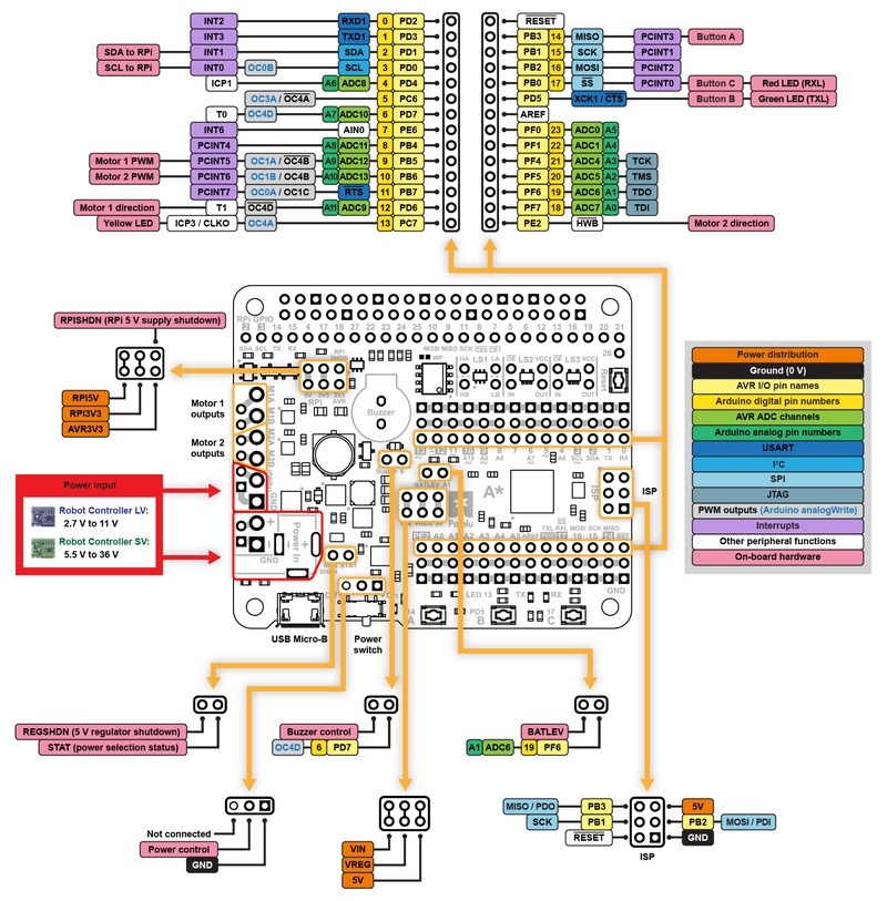
Luckily, Pololu has this handy User’s Guide where they document what resources are used on the microcontroller, the pinout, and other helpful information. They had the following graphic on their site:

So, I’m looking for 4 pins for the 2 encoders on the microcontroller that are interrupts (INT). Pins 0-3 are available, but 2 and 3 are used for Raspberry Pi communication. 0 and 1 are used for UART communication, and the gyro sensor I bought for measuring the angle can use either UART or I2C to transfer data. Pins 7-11 are interrupts, but 9-11 are taken up for UART and motor control. The only interrupt pins left are 14-17, and they’re right next to each other! Even though those pins also serve as SPI communication protocol pins, I don’t have a use for SPI, so I’ll use those pins for the encoders.
After writing the code for the encoders based on the tutorial I linked, I modified Pololu’s example to send the encoder data over the I2C link to the Raspberry Pi to display on the website. A good check to see if the encoders work is to calculate how many encoder ticks are in one full wheel revolution and see empirically if the measured encoder counts match.
The encoder’s page states that the encoder has 12 CPR (counts per revolution) or 12 ticks per revolution. The motor I bought has a extended shaft on the back that turns at the speed before the gearbox reduces it. With a 150:1 gearbox ratio, every turn of a wheel attached to the motor results in the encoder turning 150 times. This means that every wheel revolution is equivalent to 150 * 12 ticks or 1800 ticks because of the gearbox.
Good news! Turning the wheel one full revolution results in approximately 1800 ticks. :)
Another experiment worth doing is testing how many ticks results in a certain distance traveled. I bought 90 mm diameter wheels, which have a circumference of 11.12 in. There are 1800 ticks in a complete wheel revolution and the wheel should travel 11.12 in. 1800 ticks / 11.12 in is about 162 ticks / in. When I tested this movement, I got closer to 158-160 ticks / inch. This could be due to the wheel’s grip, or the weight of the robot, or just the encoders being off. Most likely, this small discrepency is due to the user’s error with measurements. :)
Next post will focus on actually getting our robot to do things with state machines!
Check out other posts in this series
Join me in learning about how computers work
Just enter your email into the box below. You'll also receive my free 12 page guide, Getting Started with Operating System Development, straight to your inbox just for subscribing.
